R3D Align and Jmol
R3D Align uses the Jmol java applet for 3D visualizations. There are many resources for learning about Jmol available on the web, here we will focus on some R3D Align-specific aspects of using Jmol.
R3D Align alignments are split into 4 models
To interact with the PDB files produced by R3D Align in any 3D viewer, including Jmol, it’s important to know that the alignment is split into 4 models:
- model 1.1: aligned nucleotides from molecule 1
- model 1.2: unaligned nucleotides from molecule 1
- model 1.3: aligned nucleotides from molecule 2
- model 1.4: unaligned nucleotides from molecule 2
Since Jmol does not draw the backbone lines across models, the backbone is depicted as discontinuous between aligned nts of the first molecule and the unaligned nts of the same molecule (models 1.1 and 1.2, 1.3 and 1.4). Strictly speaking, this is incorrect, but it facilitates identification of the boundaries between the aligned and unaligned nucleotides.
Tutorial
In this brief tutorial we will highlight the local nature of the 3D alignments produced by R3D Align and demonstrate several Jmol commands.
First, go to the R3D Align results page showing the alignment of two 16S rRNA from T. thermophilus (PDB 1FJG) and E.coli (PDB 2AW7).
In this example we will focus on two conserved internal loops. Right click on the Jmol applet to launch the console, then enter the following commands (you can also drag the commands onto the console window):
# select the first internal loop
select 1416-1419/1.1, 1481-1484/1.1;
define il1 selected;
# select the second internal loop
select 1416-1419/1.3, 1481-1484/1.3;
define il2 selected;
# center and zoom on the superposed loops
center 1418/1.1;
zoom {il1} 0;
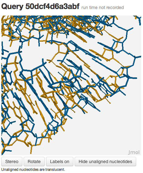
You should see something like this:

You may be wondering why the 3D structures are not superposed very well. This happens because the two RNA molecules are superposed using rigid-body superposition based on the nucleotide-to-nucleotide alignments determined by R3D Align. This means that the alignment may not be locally optimized. To see the local alignment, enter the following commands:
# superpose the internal loops using the phosphate atoms as reference points
# il1 and il2 must have the same number of atoms for this command to work
for (var i = 1; i < 3; i++) {
x=compare({il1.P},{il2.P});
select 1.1;
rotate selected @{x};
}
# show labels
select {*.P/1.1};
label %[sequence]%[resno];
color labels black;
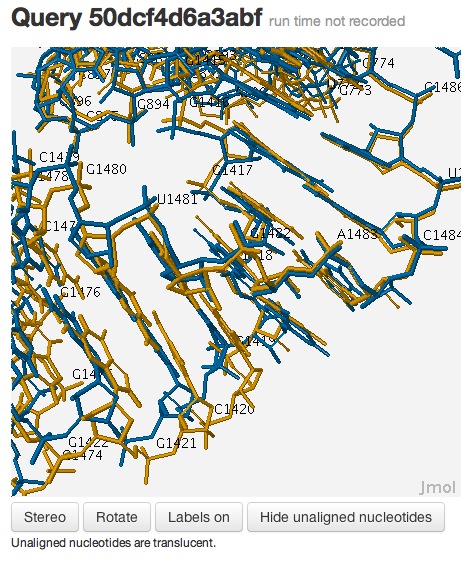
Now the superposition looks much better, and it’s clear that the internal loops are, indeed, conserved:

This example demonstrates that one needs to examine the local context of the 3D alignments to evaluate the local quality of the alignment, which may not be accurately captured by global measures, such as RMSD.
Useful Links
Jmol Tutorial Help
Select commands
Jmol scripting documentation
Updated: 08/01/2025 05:42PM
